Lab 2: Introduction to OpenGL/JOGL
CS 445: Computer Graphics,
Fall 2010
[previous lab][schedule][next lab]
Assignments are due at the beginning of class on Sept 28 (part 1), Oct 5 (part 2), and Oct 12 (part 3).
For details on what to turn in, see the Deliverables section at the bottom of each part.
Goals
- Understand the structure of a basic OpenGL program
- Simple geometric modeling and transformations
- Setting up the camera
- Understand scene graphs and hierarchical modeling.
|
SimpleJOGL
| Netbeans makes it possible for you to automatically generate a number of JOGL examples.
In this part of the lab, you are to generate the Simple JOGL Application as follows. In Netbeans, go to the menu
File; New Project. Under "Categories" choose Java. Under "Projects" choose JOGL Application. Click the "Next" button
and continue as usual to create a new project. Run the program and look through the code. Your job is to try to understand what each part of the code is doing.
We will go over it in class as well.
If you have netbeans on your own computer, you can install JOGL by
downloading the Netbeans OpenGL Pack.
Once you down load it, unzip it. Then, in Netbeans, go to the Tools->Plugins, choose the "Downloaded" tab.
Click on the "Add Plugins" button. Browse for the files you just unzipped and select them all. Then in the Plugins
tool, check them all and click "Install". Some of them may not work (e.g. GLSL Editor). If so, just skip them.
If you are missing the java docs for Jogl, here they are: jogl-1.1.1-docs.zip.
For those of you who are not using Netbeans, here is the code that Netbeans generates:
SimpleJOGLApp.java.
I believe you will need the libraries jogl.jar and glugen-rt.jar.
|
|
Animation about y-axis
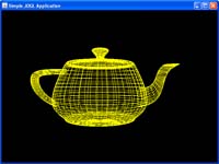
glutWireTeapot
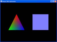
A simple modeled scene
| To explore what the code is doing, try experimenting by making small changes. For example:
- Run the program and resize the window. What happens? The resize behavior is controlled by the
code in the reshape method.
Do you understand the code? For example, what
happens when
h = (float) width / (float) height;
is replaced with
h=1;
Try changing other things such as parameters in the lines
gl.glViewport(0, 0, width, height);  or
glu.gluPerspective(45.0f, h, 1.0, 20.0);
- A really good tutorial for illustrating the effect of some of these parameters is
the Projection Tutorial written by Nate Robbins (http://www.xmission.com/~nate/tutors.html).
Download the executables for your computer type, then run projection.exe. Pay attention
to how gluLookAt is used.
- In SimpleJOGLApp, put gluLookAt in the display method and change the parameters to
move the camera around:
GLU glu = new GLU();  // put this at beginning of display
glu.gluLookAt(0,0,-20, 0,0,0,0,1,0 ); // put after glLoadIdentity
- You can also move the objects in the display method using rotate, scale, translate.
- Animation is actually turned on but nothing moves because you don't ever change what is drawn.
Try changing what is drawn, for example, by adding the following lines in the display method (where you put these lines is important!):
angle += 1;  // first need to declare angle globally
gl.glRotated(angle, 0, 1, 0);
- Add glut objects (e.g. teapots, spheres, boxes, etc).
|
The goal in this part of the lab is to understand 1) the structure of the code 2) how to specify the camera
projection, 3) how to move the camera
and objects, and 4) how to create objects (geometry and color) using glut or glBegin/glEnd. Note, there are
no lights - we will discuss lighting later on. Without lights, solid glut objects will
appear flat. It is easier to see the 3d structure if you use wireframe objects rather than solid.
To illustrate your understanding of the above, create a
simple scene using multiple built-in objects and/or simple shapes you create by specifying vertices with
glBegin/glEnd.
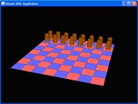
Optional: Speed is critical when it comes to computer graphics. Create a simple scene such as a large plane with
lots of teapots either randomly placed around the plane (don't worry about intersections) or placed in a grid arrangement.
Have the entire scene rotate around the y axis.
How many teapots do you have to include before the rotation starts to slow down? What if the teapots are replaced with rectangles?
Heads-up: Specifying vertices using glBegin/glEnd is called immediate mode. While
very convenient and easy to understand, immediate mode is very, very slow and is being deprecated (along with lots
of other useful things) in the later versions of opengGL (e.g. 4.1). To compare other ways of
specifying vertices, we will look at generating a cube. The code is
here. We will look at it in class.
At this point, you do not need to understand all the details of this code but
but you should be aware that things using OpenGL is becoming more complicated because many simple (but slow) features are
going away ... Of course, many really cool features are being added.
Part 1 Deliverables: By class time on Sept 28, be prepared to demo several sample images of what
you generated and at least one animation. Nothing will be collected. This lab will graded as pass/fail -
you will get credit if you can demo a program that demonstrates your basic understanding of the above items.
| 
|
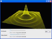
Download and run WaveJOGL.zip. It shows how one can plot a function of 2 variables.
This program loops over an (x,y) grid to calculate
the height z = f(x,y) and then plots (x,y,z) (actually, at each iteration, 4 points forming a square are calculated).
What happens if you comment out
gl.glEnable(GL.GL_DEPTH_TEST); in the init method. Let the program rotate fully using the
checkerboard pattern.
Once you understand the wave program, do one of the following projects:
|
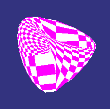
Steiner's Roman Surface |
Project 1: Plotting an Algebraic Surface: The wave program loops over an (x,y) grid to calculate
the height z = f(x,y) and plot the point (x,y,z). In this part, you are to extend this idea by looping over
a grid of parameters (e.g. r,t) and at each r,t calculate the xyz value. For example, look at
Steiner's Roman Surface on the web page discussing affine trig parameterization of the surfaces at
Steiner Surfaces. Create a wireframe to start, then experiment with using different ways of representing the vertices (points, quads, etc). If you use quads, you will have to play around with the color so that you can see detail.
|
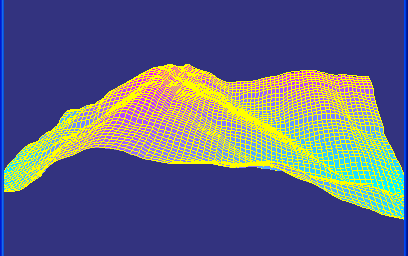
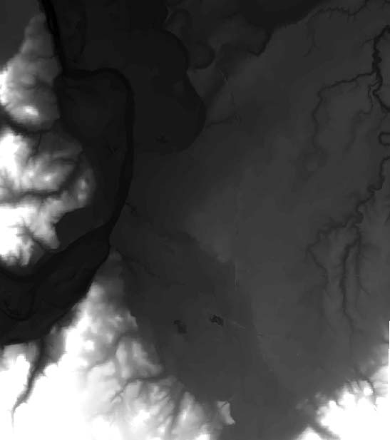
Somewhere in Colorado |
Project 2: Digital Elevation Models:
Read in either an ascii or image dem map. Sample ascii data is here.
The first two numbers are the number of columns and rows. A snippet of code for reading in this file is given
here. Note, this is not complete code - it includes the necessary imports and a method for reading the ascii file.
Depending on how comfortable you are with java, you might want to read in a DEM image (e.g. see
the image for Salem) and plot that.
This is challenging and if you aren't careful, will result in memory overflows. One should really use Vertex Arrays rather than Immediate Mode.
|
Optional: Following the cube example (see Heads-up in part 1), convert the above code to Vertex Arrays or Vertex Buffer Objects.
Part 2 Deliverables: By class time on Oct 5, submit your code (with a working jar file) to wise.
You will be evaluated based on the readability of your code as well as what the code does.
A high-strung robotic arm.
|
In class we will see how to create and implement the scene graph for
a simple solar system and a robotic arm. In this part of the lab, you are to model an object
of your choice. It should be built of multiple components and have only a few
moveable parts. It's movement should be hierarchical. For example, the top of the robot arm automatically moves when
the middle part or the arm moves. The object you create might be a simple humanoid with moving legs,
a car with moving wheels and a door that opens, or a helicoptor
that can move forward/backwards and has moving rotors. Once you decide on your object,
follow the steps below.
|
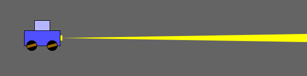
Moving car with headlight.
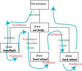
Simplified Scenegraph for Car
|
Process for Modeling Hierarchical Structure:
-
Object Design: Draw a rough picture of the
object, labeling the size and location of all components as well as
all angles or directions where movement will take place. Pay attention to where the
pivot points are.
-
Scene Graph: Using your picture as a reference,
draw a scene graph being careful to include all shapes and transformations.
For example, for a simple 2d moving car (done in Processing) we have the
simplified scenegraph in the image on the left. You should be more specific, i.e. give the value of the parameters for all
of the
transformations.
-
Implementation: Based on the scene graph, implement the object in OpenGL. User controls
may be implemented either through buttons or key presses. Alternatively, you can have the
motion be done automatically by a procedural algorithm. It is important to
keep your code clean. Use the robotic arm code as an example of how to organize
your code. Include enough comments in your code so that someone reading it
can understand what it is doing.
|
Part 3 Deliverables: By classtime on Oct 16, Submit your Netbeans project to Wise. Be sure to include a working jar file.
Also include as attachments, both the object design and the scene graph. If you drew them on paper, you can scan them
or turn in the paper copy. You will be evaluated based on the organization of your scene graph, its clean implementation in the
code, and the complexity of what you create.
[top] [Schedule]
[Home]