 |
Lab 2: Getting Started with OpenGL
|
|
Lab 2: Getting Started with OpenGL
|
In this lab, you are to create two solid geometric shapes (a Disk shape and one other shape of your choice), together with a wire frame version of one of these objects.
Note, if you are using your own computer, you need to make sure that you have the glew libraries installed. Also, if your computer does not run OpenGL 3.2 or later, you will either need to update your graphics card driver, or use a different version of the shader code. If you are not certain which version you are running, you can try using the OpenGL Extensions Viewer
This lab does not require a lot of programming. You are, however, expected to really dig through the code to understand what it does. This will take time and will probably require that you ask a lot of questions. The more you try to understand now, the less confused you will be later on.
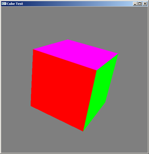
Become Familiar with the Code: Download and run the Codeblocks Cube Project. It is a simple program that displays a cube. By pressing the "x", "y", and "z" keys on the keyboard, the user can rotate the cube about the x, y, and z axies. Press "r" to reset. Note, the rotation about x is always performed first, followed by y, then z.
Students in IDS352: Can you get gimbal lock to occur?
Generate Two New Shapes:
 |
 |
 |
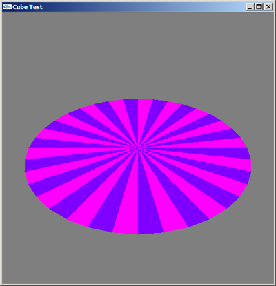
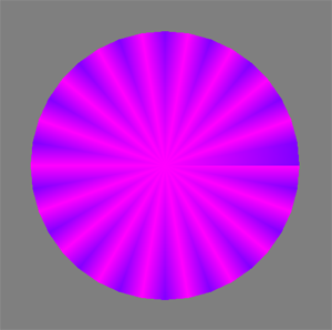
| A rotated disk. The colors show the triangle structure. | A disk created using GL_TRIANGLE_FAN instead of GL_TRIANGLES (see
discussion below). |
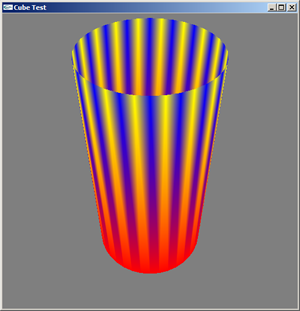
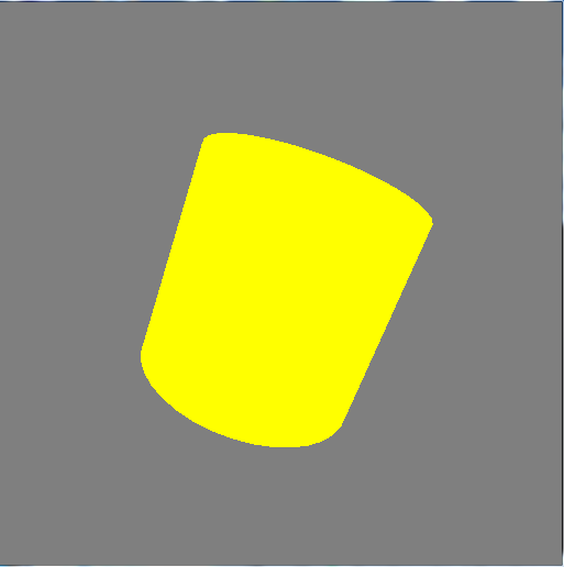
A flaming cylinder! |
All of the geometric shapes inherit from the GeometryBase class. And, all of the shader setup is done in the GeometryBase class, which you don't really have to touch at the moment. However, you will need to understand it later so please read through this class carefully so you know what it is doing.
The number of slices for disk (or cylinder) should be an input so that you can vary the smoothness of the boundary. Given the number of slices, make sure you know how many total vertices will need to be stored. Note, there are two ways of drawing the disk - one using GL_TRIANGLES and the other using GL_TRIANGLE_FAN. The number of vertices will be different for each. GL_TRIANGLE_FAN is a much more efficient way of storing the vertices. However, one cannot have each triangle colored distinctly, as in the picture above (left), because each now vertex is shared by more than one triangle (yet can have only one color associated with it). The closest one can get is the image in the middle.
The arrays will have to be created in the constructor.
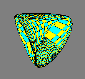
For a particular challenge, try a steiner surface. Look at the equations that describe the function in terms of 2 parameters, u and v. You will need a nested loop over these 2 variables. For each (u,v), calculate the vertex and normal. Recall the normal is given by the gradient of the function. Of course, for this lab, we aren't using the normals so you won't be able to test them until a later lab.
Generate a Wired Shape:
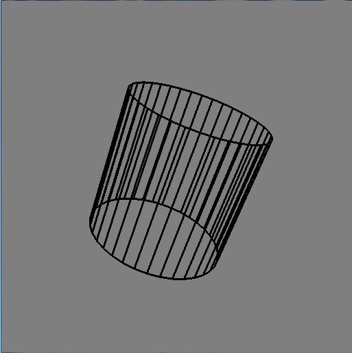
Wired geometric shapes are all black, use the mode GL_LINES, and do not need normals. Create a WiredGeometryBase class to serve as the base class for your wired shapes. You can start with a copy of the GeometryBase class and delete the parts you don't need. To do this, you need to be careful about what you keep and what you delete. Once you have the WiredGeometryBase class, create a subclass (e.g. WiredCylinder) for at least one of your geometric objects. Draw the solid and the wired shapes together so you can see the geometry better. You can increase the line width by placing the following command in the init method
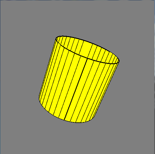
Demonstrate your program in lab no later than 5pm on Tues, Sept 30. Before the demo, generate several images showing the disk and your other object either in separate images or together in one image. One of your images should show an object with the wireframe on top of the shaded. Zip together the images and your codeblocks project (please delete the bin and obj folders) and submit via WISE.
One generally does not generate complex organic models directly in openGL. Instead the models are either scanned (e.g. see The Stanford 3D Scanning Repository) or are modeled in programs such as Maya (and exported, e.g. to obj format). The ply and obj formats can then be read into your OpenGL program. One can find c++ libraries which will read ply and obj files, or you can write your own.
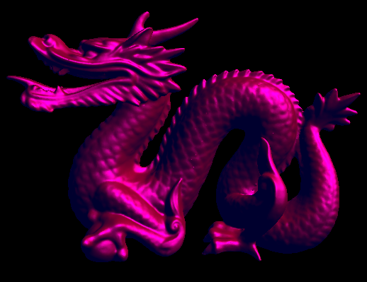
Dragon |
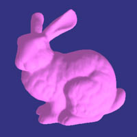
Bunny |
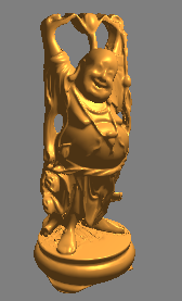
Buddha |
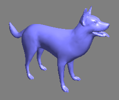
Dog |
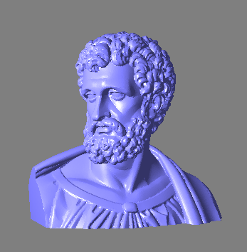
Bust |