
Milestone 4: The whole path
Once you have completed Milestone 3 (and thoroughly tested it against the online demo!), you are ready to tackle the complete Enigma encryption path. Pressing a key on the Enigma keyboard sends a current from right to left through the fast rotor, through the medium rotor, and through the slow rotor. From there, the current enters the reflector, which has its own internal wiring offsets:
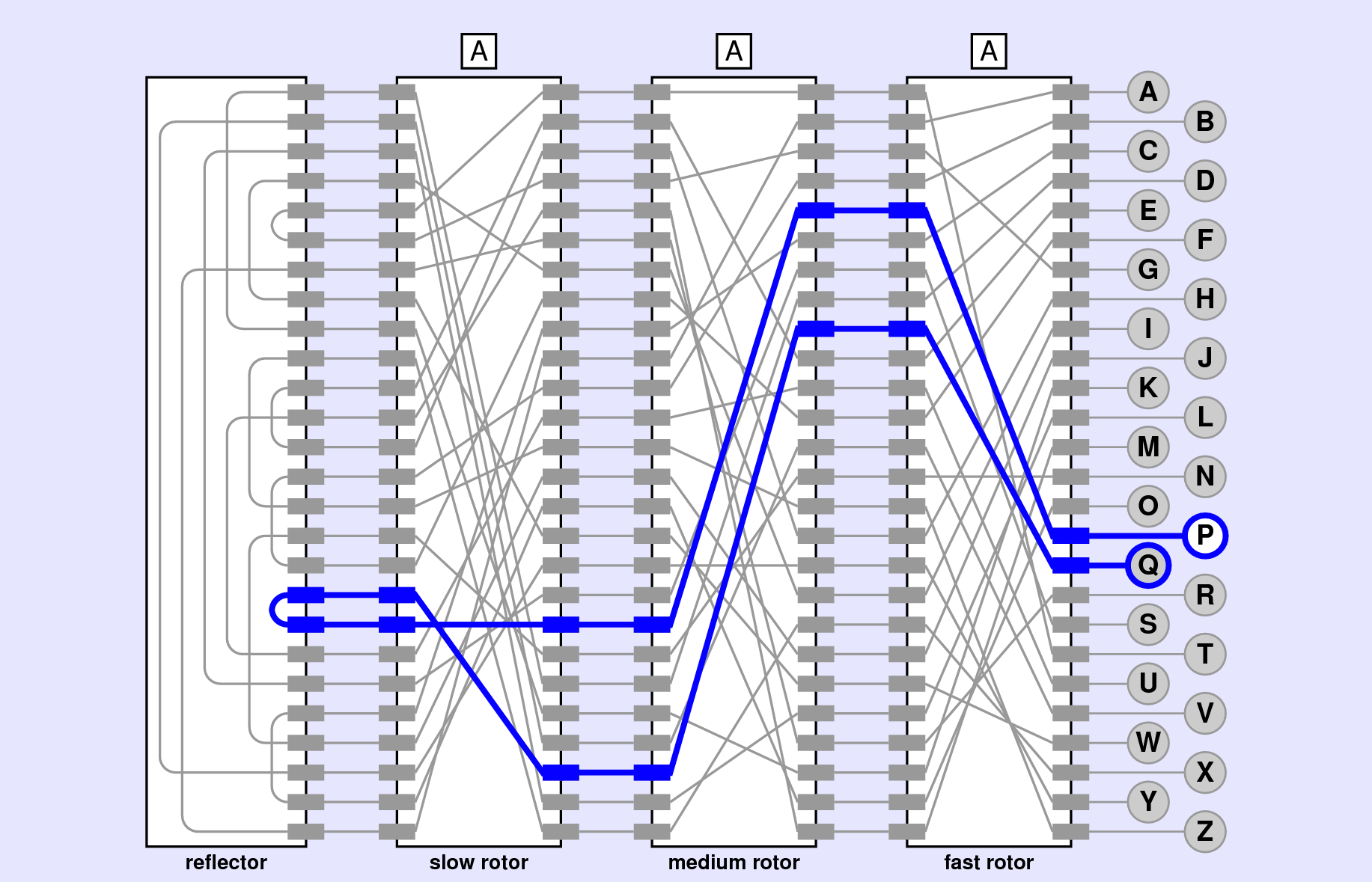
REFLECTOR_WIRING=[ 8,22,18,4,1,25,19,22,18,5,2,8,24,3,21,7,23,1,25,18,8,3,19,4,23,7 ]When the current leaves the reflector, it makes its way back from left to right, starting with the slow rotor, moving on to the medium rotor, and finally passing through the fast rotor to arrive at one of the lamps. The complete path that arises from pressing Q is illustrated in Figure 1. As you can see from the diagram, the current flows through the fast rotors from right to left to arrive at I (index 8), through the medium rotor to arrive at X (index 23), and through the slow rotor to arrive at R (index 17). It then makes a quick loop through the reflector and emerges at S (index 18). From there, the current makes its way backward through the slow rotor straight across to S (index 18), through the medium rotor to E (index 4) and finally landing at P (index 15).
Q.
If everything is working from your previous milestones, making your way through the rotors from right-to-left and then the reflector should not be too difficult. The challenge comes when you need to move backward through the rotors. The wiring offsets as given in EnigmaConstants.py show how the contacts are connected when you move right to left. When the signal is running from left to right, however, you can not use same wiring offsets directly, because the translation has to happen “backwards.” What you need is the inverse of the original wiring offsets.
The idea of inverting wiring offsets is most easily illustrated by an example. Suppose that the right-to-left wiring offsets are:
[3,24,13,14,2,25,3,15,11,17,6,25,22,24,7,16,17,11,0,21,7,18,16,23,0,24]which could be visualized as:
The easiest way to create the reversed wiring offset list is to look at each of the original offsets, to see where they point. That will represent the index we want to modify in the reversed wiring offset list. For example, in the above list of offsets, the first offset is 3, so we will want to set index-3 in our reversed wiring offset list. But what do we set it to? Well, if you look at index-3 in the bottom of the diagram, it connects back to index-0: or, in otherwords, it has an offset of -3.
rev_offsets = [_,_,_,-3,_,_,_,_,_,_,_,_,_,_,_,_,_,_,_,_,_,_,_,_,_,_]So far we have been dealing only with positive offsets, but there is nothing wrong with negative offsets either. However, we could convert this to a positive offset if we wanted by just instead doing 26 - 3 = 23.
If we look at the next wiring offset, it is 24. So we can do the same task of updating index-24 in the reverse offsets list and setting it equal to -24 (or 26-24=2).
rev_offsets = [_,_,_,23,_,_,_,_,_,_,_,_,_,_,_,_,_,_,_,_,_,_,_,_,2,_]We can keep this process going until we have populated the entire list of reverse wiring offsets.
Since this process is most useful with the rotors, it probably makes the most sense to define it as a stand-alone function called invert_offsets inside the EnigmaRotor.py file where your EnigmaRotor class lives. You could compute the reverse offsets every single time you need it from the current rotor’s wiring offsets, or you could compute it once at the start, and then advance both forward and reverse wiring offset lists whenever the rotor advances.
My recommendation is to compute it once at the start, and save it as another attribute to your rotor class. Then you can define another method left_to_right which takes an index as an argument and returns what the resulting index on the right side of the rotor would be. This would look identical to right_to_left, except it would look up the offset from the reverse wiring offsets list instead of the original.
Then, when you pass the signal through the rotor from left to right, you can just use the newly defined method. And now you can construct the full encryption path! As shown in Figure 1 above, if your rotors all start at A, then pressing the Q key should result in the P lamp lighting up. Try changing each of rotors: changing any rotor should change which lamp lights! Test things against the online demo!!